A concrete thermal control plan defines how a project will predict, limit, monitor, and respond to heat development in mass concrete. It connects the approved mixture, placement conditions, thermal model, control measures, sensor layout, responsibilities, and acceptance criteria in one controlled document.
The plan should be completed and approved before placement. Its requirements must match the governing specification, structural geometry, available equipment, expected site conditions, and project-specific thermal analysis. It does not replace the project specification or the judgment of the responsible engineer.
What Problems Must a Mass Concrete Thermal Control Plan Solve?
The plan must control two separate quantities: the maximum concrete temperature after placement and the temperature difference between critical interior and near-surface locations. Controlling one does not automatically control the other.
The plan must also define how compliance will be predicted, measured, documented, and maintained until the specified completion criteria are satisfied.
Excessive Maximum Internal Concrete Temperature
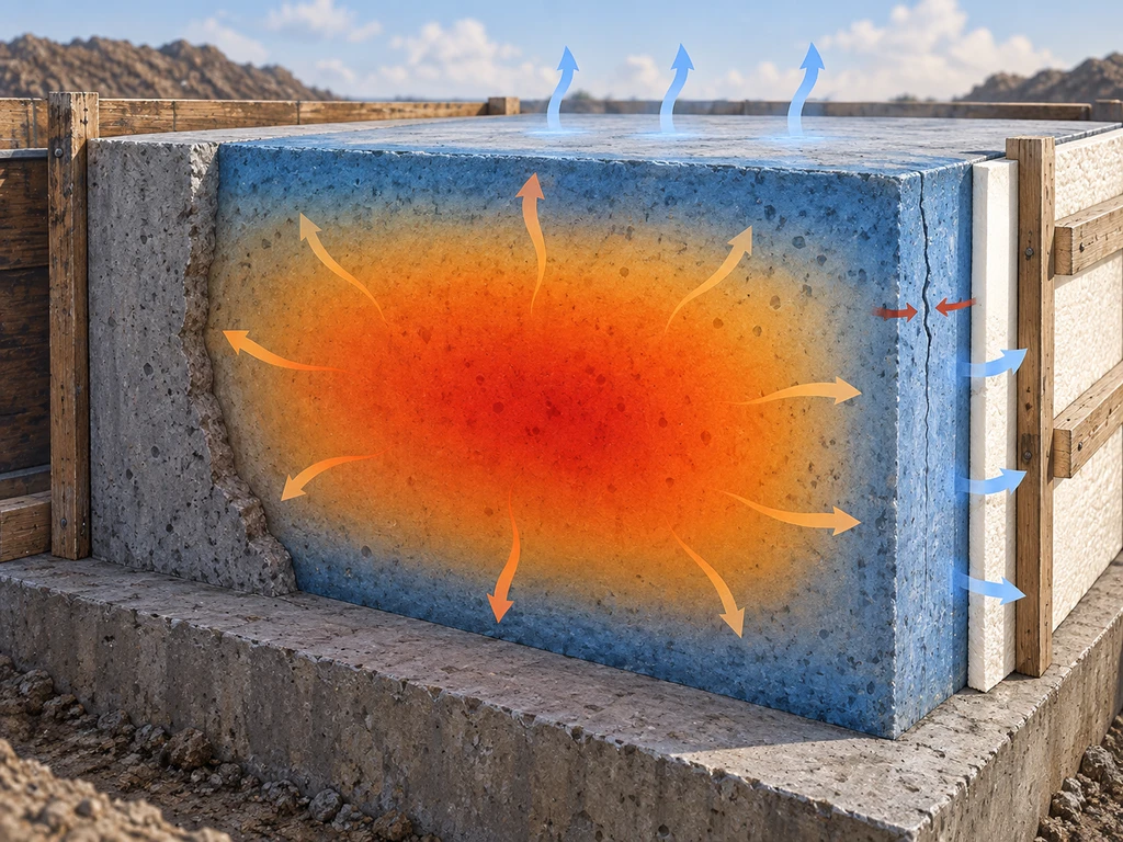
Cement hydration generates heat. In a large placement, the interior may generate heat faster than it can release that heat through the surrounding boundaries. The resulting core temperature depends on the mixture’s heat-generation characteristics, initial concrete temperature, element size, insulation, construction sequence, and heat loss through each face.
The governing limit must come from the contract documents. Where ACI SPEC-301-20 applies, commonly cited default limits are 160°F (70°C) for maximum concrete temperature after placement and 35°F (19°C) for the center-to-surface temperature difference. These values are separate limits and are not universal requirements for every project, specification, or cementitious system.
Excessive internal temperature can affect long-term performance and may increase the risk of temperature-related durability problems in susceptible concrete. The plan should therefore identify the applicable limit, where it will be measured, how the predicted peak will be verified, and who has acceptance authority.
Excessive Core-to-Surface Temperature Differential
The surface of a mass concrete placement often cools faster than the interior. When the cooler surface tries to contract while the warmer core restrains that movement, tensile stress can develop before the concrete has gained sufficient tensile capacity.
Insulation can slow surface cooling and reduce the temperature gradient. Precooling and mixture adjustments can reduce core heating. The plan must evaluate both sides of this relationship because lowering the placement temperature alone does not guarantee that the later core-to-surface differential will remain acceptable.
The allowable differential is a project control value rather than a universal crack-prediction constant. Actual cracking risk also depends on restraint, concrete tensile strength, elastic properties, creep, cooling rate, geometry, and boundary conditions.
Which Project Conditions Drive the Thermal Risk?
Thermal risk is controlled by the interaction of the concrete mixture, initial temperatures, structural geometry, heat-flow boundaries, construction sequence, environmental exposure, and response capability. No single member thickness or ambient-temperature threshold defines every mass concrete placement.
The thermal control plan should identify the assumptions used for each of these conditions so actual field conditions can later be compared with the approved analysis.
Concrete Mixture and Heat-Generation Characteristics
Collect the cementitious-material types and quantities, water content, aggregate proportions, admixtures, expected strength development, and relevant thermal properties of the proposed mixture.
Heat-generation data should represent the production mixture rather than generic concrete. Depending on the project requirements, the supporting data may come from laboratory calorimetry, adiabatic or semi-adiabatic testing, trial batches, validated historical data, or another method accepted by the responsible engineer.
The plan should also identify which mixture changes require review. A change in cement source, supplementary cementitious material, cementitious content, admixture, aggregate source, or mixture proportions may alter the predicted temperature curve even if the specified compressive strength remains unchanged.
Initial Concrete and Ingredient Temperatures
Record the expected temperatures of cementitious materials, aggregates, mixing water, and fresh concrete at the applicable discharge and placement points. These values establish the starting conditions for the thermal analysis.
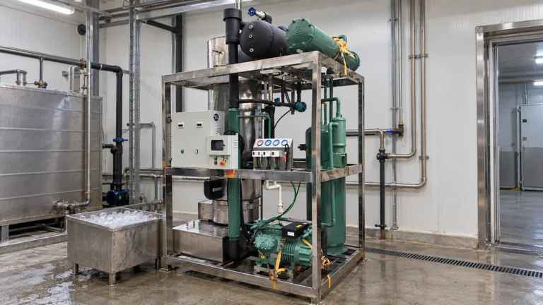
When ice replaces an approved portion of the mixing water, include it in the total water balance. Determine the required ice quantity from an approved batch heat balance, then verify that production, storage, weighing, and delivery capacity can satisfy the peak batching period.
Available flake ice machines should be screened against calculated batch demand and site conditions rather than selected from nominal daily tonnage alone.
Structural Geometry and Boundary Conditions
Model the actual lift dimensions, construction joints, foundation interface, exposed faces, formwork, insulation, and adjacent placements. The analysis should represent the intended construction condition rather than an isolated block with uniform boundaries.
Rock, soil, water, previously placed concrete, removable forms, insulation, and exposed air can create different heat-loss conditions around the same placement. Corners, edges, lift interfaces, penetrations, and embedded systems may also create local temperature patterns that are not represented by nominal member thickness alone.
The plan should identify the predicted hot locations and the surface or boundary locations used to calculate the governing temperature differences.
Placement Sequence, Schedule, and Environmental Conditions
Include the planned lift sequence, batch rate, pour duration, time of day, delivery cycle, curing period, expected form-removal timing, and relationship to adjacent placements.
Evaluate credible hot and cold environmental cases. Air temperature, wind, rain, solar exposure, ground temperature, and rapid weather changes can affect surface cooling and the required protection. Seasonal averages alone may not represent the conditions that control the maximum temperature or maximum differential.
The approved analysis should also define the range of conditions covered by the plan. Conditions outside that range should trigger review rather than an unapproved field adjustment.
Monitoring, Response, and Coordination Requirements
Define who reviews temperature data, who receives alarms, who verifies questionable readings, who can adjust approved cooling or insulation measures, and who may delay or stop a placement.
The communication and response chain must remain functional during nights, weekends, shift changes, power failures, and communication interruptions. The plan should include current contact information, backup data access, escalation requirements, and the records required for each response.
How to Build a Mass Concrete Thermal Control Plan
Build the plan by establishing the governing criteria first, then collecting project inputs, analyzing temperature development, selecting compatible controls, and documenting the monitoring, response, approval, and closeout requirements.
Each assumption should be traceable to a drawing, specification, mixture record, test result, calculation, manufacturer’s verified equipment data, or other accepted project source.
Step 1: Confirm the Scope, Criteria, and Responsibilities
Identify every placement covered by the thermal control plan. Record the governing specification, maximum temperature, allowable temperature differential, measurement locations, monitoring duration, reporting frequency, completion criteria, and approval authority.
Assign responsibilities among the engineer, contractor, concrete producer, testing agency, thermal consultant, monitoring provider, and cooling-system operator. Responsibility should be defined for:
- Approving the mixture and thermal analysis.
- Confirming production and cooling capacity.
- Installing and checking sensors.
- Reviewing temperature data.
- Receiving warnings and alarms.
- Authorizing control adjustments.
- Evaluating exceedances and missing data.
- Approving protection removal and thermal closeout.
The plan should distinguish between personnel who collect information and personnel who are authorized to make acceptance or control decisions.
Step 2: Collect the Placement, Mixture, and Environmental Inputs
Compile the current drawings, lift dimensions, reinforcement congestion, construction joints, foundation conditions, form and insulation properties, mixture proportions, heat-generation data, ingredient temperatures, placement rate, curing method, environmental cases, and equipment limits.
Inputs should be internally consistent. The planned placement rate, for example, must align with the pour duration used in the thermal model and the production capacity used to calculate precooling demand.
Missing or assumed heat-generation, boundary, or material-property data should be identified clearly. Because these inputs directly affect predicted peaks and gradients, unresolved assumptions should not be hidden inside the model or treated as verified project data.
Step 3: Model the Temperature Development and Select Control Measures
Use a documented thermal model to predict temperature versus time at critical interior, surface, and boundary locations. Record the model geometry, thermal properties, heat-generation inputs, initial temperatures, boundary conditions, construction sequence, insulation assumptions, and environmental cases.
Check predicted maximum temperatures, temperature differences, timing, and cooling trends against laboratory data, a qualified mock-up, validated project records, or an accepted comparable placement. The validation method and its limitations should be stated in the plan.
Evaluate practical combinations of:
- Lower-heat mixture design.
- Reduced placement temperature.
- Chilled mixing water.
- Ice substitution for an approved portion of mixing water.
- Aggregate cooling.
- Lift or sequence adjustments.
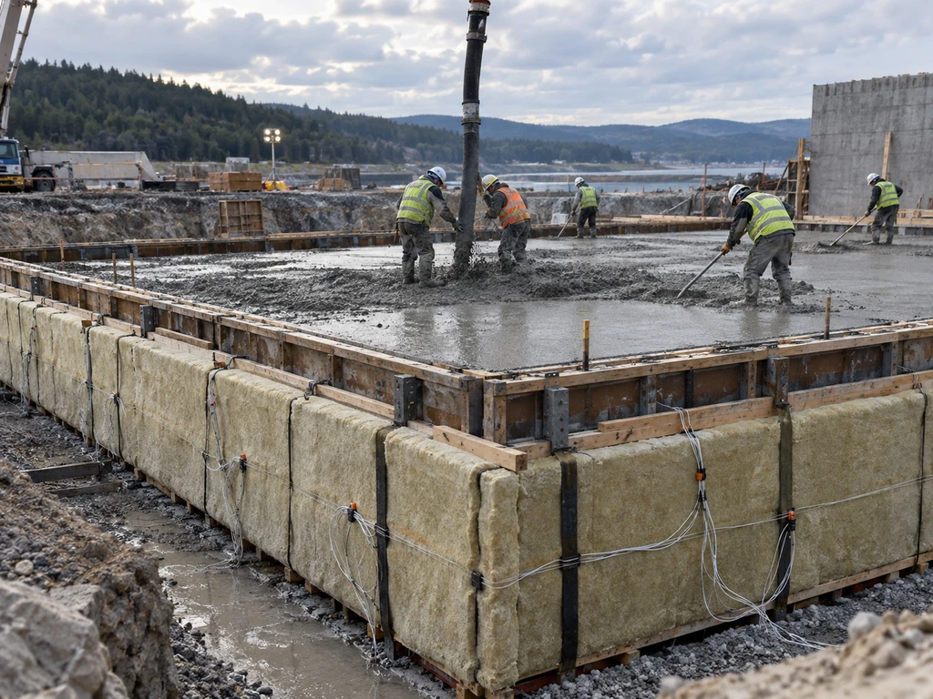
- Surface insulation.
- Delayed form or insulation removal.
- Embedded-pipe cooling.
Each measure should be selected for a defined purpose. Precooling lowers the starting temperature, while insulation limits rapid surface cooling. Embedded-pipe cooling removes heat from the interior but requires engineered flow, temperature, operating, and shutdown criteria. One measure should not be adjusted without considering its effect on the others.
Where ice precooling is selected, calculate the approved ice requirement per batch and the peak demand per hour. Verify production capacity, storage, recovery, weighing accuracy, delivery, water balance, utilities, and expected performance under actual site conditions.

Step 4: Define the Sensor Layout, Monitoring, Escalation, and Response Plan
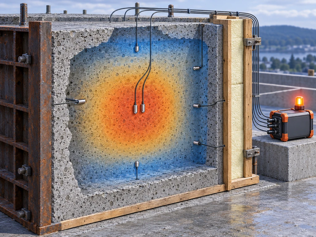
Place sensors at predicted hot spots, representative near-surface locations, and boundaries needed to calculate the specified temperature differences. Provide redundant sensors at critical locations where a single failure could prevent compliance verification.
The sensor plan should document:
- Sensor identification and intended location.
- Installation depth and corresponding comparison point.
- Required accuracy or functional checks.
- Reading and reporting intervals.
- Installation protection.
- Data transmission and storage.
- Backup retrieval procedures.
- Replacement or evaluation procedures for failed sensors.
Set warning and action thresholds below the acceptance limits so the project team has time to verify the condition and apply an approved response. A warning should not automatically trigger an aggressive control change before the sensor and temperature trend have been reviewed.
Permitted responses may include checking the sensor, repairing surface protection, modifying insulation, adjusting an approved cooling system, delaying form removal, protecting an exposed face, notifying the engineer, or postponing a subsequent placement. Each response must identify the trigger, responsible reviewer, authorized decision-maker, required documentation, and any conditions that require new analysis.
Step 5: Define Completion Criteria, Compile the Plan, and Obtain Approval
State when monitoring may end, when forms or insulation may be removed, and when active cooling may stop. Completion criteria should address the recorded maximum temperature, controlling temperature differences, cooling trend, required curing or protection period, data completeness, and engineer authorization.
Where removal of protection changes a boundary condition, the plan should consider whether exposure could create a new temperature differential. A falling core temperature alone does not establish that forms or insulation can be removed safely.
Compile the calculations, assumptions, drawings, mixture information, equipment requirements, monitoring procedures, contact list, contingencies, response actions, reporting forms, and closeout criteria into one controlled document. Record the applicable revision and obtain all required approvals before mobilization or batching.
How to Verify the Thermal Control Plan
Verification must show that the approved plan is complete, executable, and based on current project conditions. A forecast that complies on paper is not sufficient if the mixture, schedule, equipment, weather, or boundaries used during construction differ from the approved assumptions.
Verification should therefore focus on whether the plan inputs remain valid and whether the required systems can perform their assigned functions.
Pre-Pour Verification
Before placement, confirm the approved mixture, current model inputs, forecast conditions, sensor layout, data-acquisition system, cooling and insulation capacity, backup power, calibration or functional records, communication chain, and response resources.
Conduct a pre-pour meeting that confirms responsibilities, decision authority, reporting intervals, warning thresholds, and contingency procedures. Test the complete monitoring path from sensor reading and data storage to alarm receipt and responsible-person acknowledgment.
Verify that the mixture, material temperatures, placement rate, equipment capacity, insulation, and weather conditions remain within the range covered by the approved analysis. Resolve material deviations before batching begins.
Verification During Placement Against the Approved Plan
Compare actual ingredient and concrete temperatures, batch rate, cooling inputs, lift sequence, environmental conditions, and sensor readings with the approved assumptions. Record deviations and evaluate whether they affect heat generation, heat loss, predicted peaks, or the locations used for acceptance.
When ice is used, verify the approved water replacement, measured ice quantity, and ability of the cooling system to support the required batching rate. Guidance on concrete cooling with flake ice explains why the batch water balance and peak delivery requirement must be established before equipment is selected.
The thermal control plan should define the review and approval process for deviations. Detailed delivery, consolidation, workmanship, and general placement procedures remain governed by the project’s mass concrete placement documents.
Post-Pour Verification and Formal Closeout
Review the complete temperature record for maximum values, controlling differentials, missing data, alarms, response actions, cooling rates, and compliance with the specified monitoring period.
Compare measured temperature curves with the predicted peaks, timing, and gradients. Investigate unexplained differences rather than assuming that a compliant maximum value validates every model input.
Formal closeout requires confirmation that the applicable completion criteria were met, deviations were resolved, and changes to insulation, forms, sensors, cooling manifolds, or other temporary systems were authorized. Retain the accepted temperature record and supporting approvals with the project documentation.

How to Keep the Thermal Control Plan Effective During Construction
The plan remains effective only when equipment stays ready, field changes receive technical review, and measured results are used to improve later placements. Approval before the first placement does not make the plan valid for every later condition without review.
Maintain Operational Readiness and Backup Capacity
Verify that refrigeration equipment, pumps, insulation, sensors, data loggers, communications, and backup power remain capable of performing their assigned functions before each covered placement.
Maintain appropriate spare sensors, replacement materials, and recovery procedures for critical failures. Backup capacity should protect the functions that control production, monitoring, or response; simply duplicating a noncritical component does not create an effective contingency.
Equipment inspections and readiness records should correspond to the requirements stated in the approved plan.
Control Field Changes Against the Approved Plan
Route changes to mixture proportions, cement source, placement temperature, lift size, schedule, insulation, form removal, cooling flow, or sensor layout through the plan’s change-control process.
Reanalyze a change when it can alter heat generation, heat loss, restraint, predicted peak temperature, temperature differential, or the locations used to demonstrate compliance. Temporary field convenience should not override a thermal assumption without the required technical review and authorization.
Approved changes should be recorded in the controlled plan or an accepted revision so field personnel and reviewers use the same requirements.
Compare Results, Capture Lessons Learned, and Update Future Plans
Compare measured temperature curves with predicted peaks, timing, differentials, and cooling trends. Where results diverge, investigate changes in materials, weather, boundary conditions, construction sequence, insulation, cooling performance, or sensor condition.
Use accepted findings to refine later placements. Update model inputs, controls, sensor locations, or response thresholds only after documenting the technical basis and obtaining the required approval.
The objective is not to force later measurements to match the original model. It is to maintain a traceable relationship between the approved assumptions, actual conditions, measured results, and future decisions.
Mass Concrete Thermal Control Plan Checklist
- Governing specification, temperature limits, measurement locations, and responsible parties are identified.
- Every mass concrete placement covered by the plan is clearly defined.
- Placement geometry, boundaries, sequence, and environmental cases match the current drawings and schedule.
- Mixture heat data and initial ingredient temperatures represent the proposed production concrete.
- Model assumptions, thermal properties, validation basis, predicted peaks, timing, and critical locations are documented.
- Control measures have sufficient production, storage, delivery, insulation, pumping, utility, and backup capacity.
- Sensor drawings define core, surface, boundary, and redundant locations.
- Sensor identification, reading intervals, data storage, backup procedures, and failure responses are documented.
- Warning levels, action thresholds, reporting, escalation, authorized responses, and decision-makers are assigned.
- Pre-pour verification and change-control requirements are defined.
- Monitoring completion, protection removal, cooling shutdown, and closeout criteria are documented.
- Approved forms are available for temperature reporting, alarms, deviations, actions, and final acceptance.
If precooling equipment is part of the approved plan, provide the required ice per batch, peak batches per hour, inlet-water temperature, storage requirement, available utilities, and site location through Mike Ice Machine’s contact page. These inputs support an initial review of production, storage, and delivery feasibility; they do not establish the project’s temperature limits or replace the approved thermal analysis.
FAQs
How Is a Thermal Control Plan Different from a Hot Weather Concreting Plan?
A thermal control plan manages internal heat development, maximum concrete temperature, and temperature gradients in mass concrete. A hot weather concreting plan addresses environmental effects on mixing, transport, placement, finishing, evaporation, and curing.
A project may require both plans. Meeting hot-weather placement requirements does not automatically control the later internal peak temperature or core-to-surface differential.
Is a Trial Placement or Full-Scale Mock-Up Necessary?
Not for every project. It may be required by the specification or responsible engineer when available mixture data, model validation, equipment trials, or comparable placement records do not adequately demonstrate the proposed controls.
The plan should identify what the trial or mock-up must verify and how its results will be incorporated into the final analysis.
Can Wireless Sensors Replace Wired Thermocouples?
Yes, if the approved wireless system meets the required accuracy, reading interval, transmission range, data retention, temperature exposure, and redundancy requirements.
Concrete depth, reinforcement, batteries, site interference, data recovery, and communication reliability should be evaluated before placement. Wireless communication convenience does not replace reliable measurement and retained records.
Can Temperature Data Be Used for Concrete Maturity and Strength Estimation?
Yes, but only after establishing a strength-maturity relationship for the actual mixture and applying the approved method.
Temperature monitoring alone provides thermal-control data. Strength estimation requires mixture-specific calibration, supporting strength tests, and compliance with the applicable project procedure and standard, such as ASTM C1074 where specified.
What Happens to Embedded Cooling Pipes After Thermal Control Is Complete?
Their final treatment must follow the approved drawings and project specification. The plan should state whether the pipes remain embedded, are drained or flushed, are pressure-grouted, and how exposed connections are removed or sealed.
Cooling shutdown and final pipe treatment should be planned before installation. They should not be improvised after thermal control is complete.
External Sources
- ACI PRC-207.1-21: Mass Concrete—Guide
- ACI PRC-207.4-20: Cooling and Insulating Systems for Mass Concrete
- ACI Technical FAQ: What Is Mass Concrete?
- ACI Technical FAQ: Temperature Limits for Mass Concrete
- ACI PRC-305-20: Guide to Hot Weather Concreting
- ASTM C1074: Standard Practice for Estimating Concrete Strength by the Maturity Method