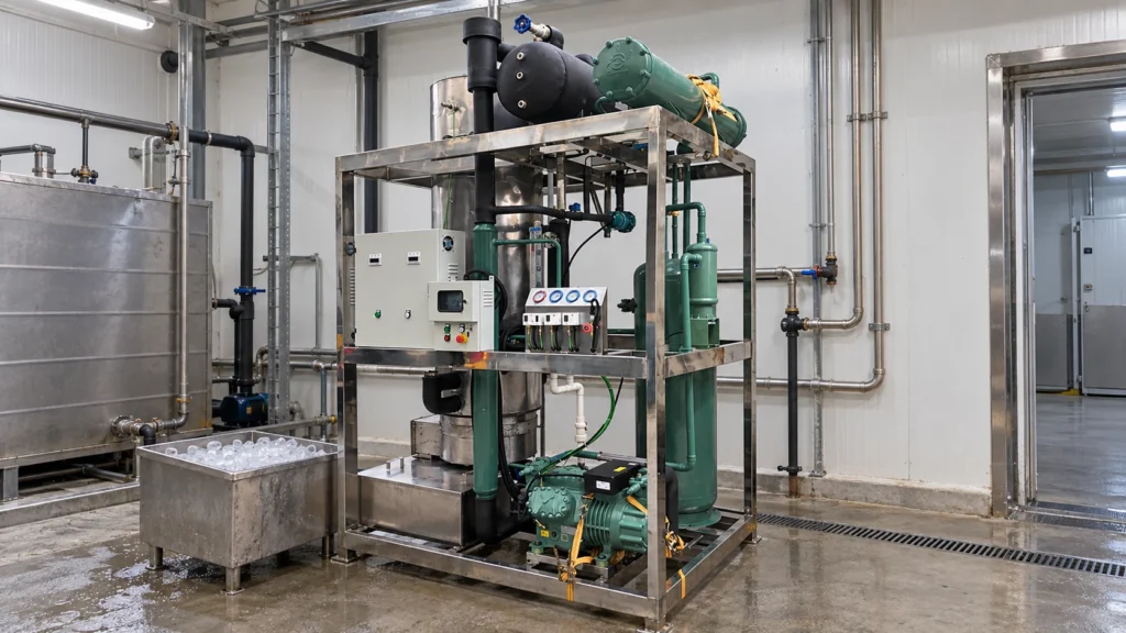
A water-cooled ice machine freezes water by transferring its heat into a refrigerant and then releasing that heat into water flowing through the condenser. In a water-cooled ice machine, condenser water replaces ambient air as the final medium that carries heat away from the refrigeration system.
The complete process involves three separate fluid circuits. Understanding how they interact helps engineers and buyers evaluate machine configuration, utilities, installation requirements, and operating conditions.
What Is a Water-Cooled Ice Machine?
A water-cooled ice machine is an ice maker whose refrigeration system uses water flowing through a condenser to remove heat from the refrigerant. The condenser water does not become ice and should remain separate from the potable ice-making water.
“Water-cooled” describes the condenser, not the evaporator or the shape of ice produced. Batch machines and continuous machines can both use water-cooled condensers. Industrial tube ice machines, for example, may use this configuration where the site can provide suitable condenser-water flow and heat rejection.
The Three Circuits That Make a Water-Cooled Ice Machine Work
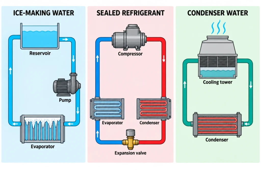
The machine moves heat through three coordinated circuits. The ice-making water gives up heat, the refrigerant carries that heat, and the condenser water removes it from the refrigeration system. The fluids perform different jobs and normally do not mix.
The Ice-Making Water Circuit
Potable or process-approved water enters a reservoir, distributor, or evaporator assembly. Depending on the machine design, a pump may circulate it across a plate, drum, cylinder, or vertical tubes. Part of the water freezes on the evaporator surface while the remaining water returns to the reservoir or leaves through a controlled purge.
Water quality affects scale formation, ice clarity, sanitation, and cleaning frequency. Treatment must suit both the incoming water and the machine manufacturer’s limits; excessive mineral removal can also change ice formation or water sensing on some models.
The Refrigerant Circuit
The refrigerant absorbs heat at the evaporator and rejects it at the condenser. The compressor raises the pressure and temperature of refrigerant vapor. In the condenser, that vapor releases heat and becomes liquid. An expansion device then lowers the refrigerant pressure before it re-enters the evaporator.
The refrigerant remains inside a sealed circuit. Its operating pressures, control method, charge, and applicable service rules depend on the specified refrigerant and system design.
The Condenser-Water Circuit
Condenser water flows through a heat exchanger and absorbs heat from the hot refrigerant. This water may return to a cooling tower or another recirculating heat-rejection system. A once-through arrangement instead discharges the warmed water after one pass, but this configuration can consume substantial water and may be restricted by local requirements.
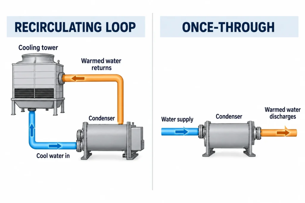
Water flow is often regulated to maintain the required condensing condition. Insufficient flow, high inlet-water temperature, fouling, or a closed valve can raise condensing pressure and reduce capacity.
How Does a Water-Cooled Ice Machine Work Step by Step?
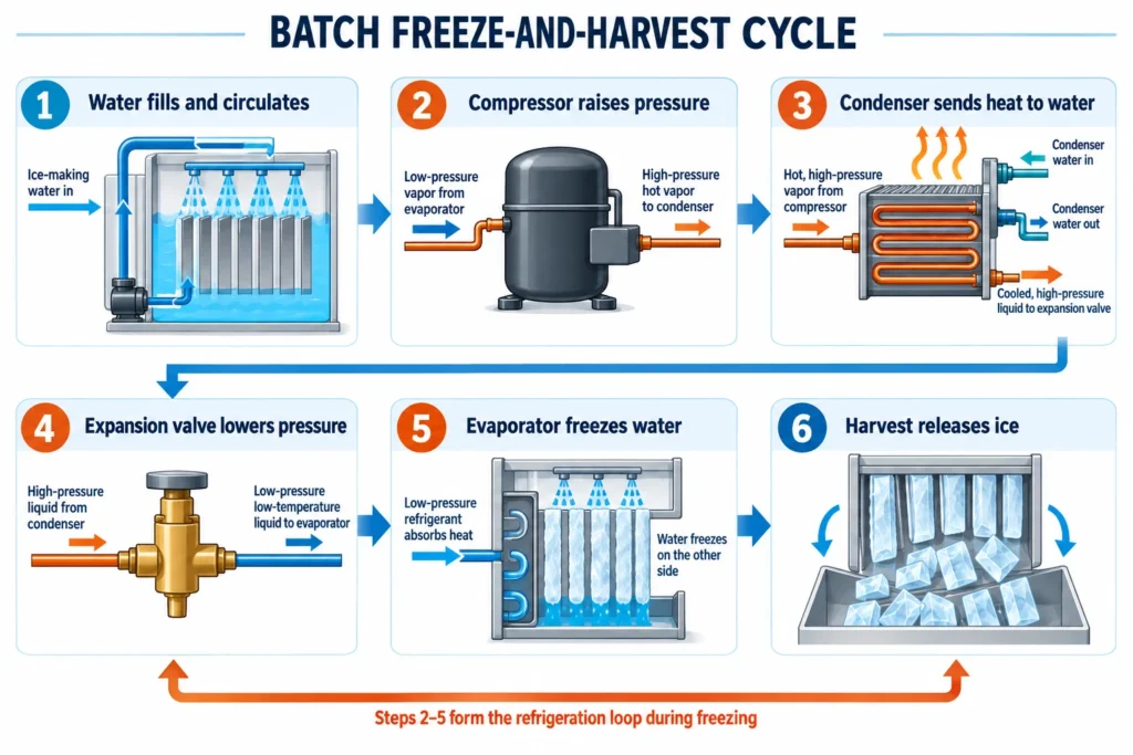
The sequence below primarily describes the freeze-and-harvest cycle used by batch machines such as cube, tube, and some plate ice machines. Continuous flake-ice machines use the same basic refrigeration cycle but form and remove ice continuously rather than through a separate harvest stage.
Step1: Fill and Circulate the Ice-Making Water
The water valve fills the reservoir or evaporator to the operating level. A pump or distribution system then delivers water uniformly to the freezing surface. Controls verify the required water level before normal freezing continues.
Poor distribution can produce uneven ice, extend the cycle, or leave parts of the evaporator dry. The cause may be low supply pressure, blocked passages, scale, or an incorrectly adjusted water level.
Step2: Compress the Refrigerant
The compressor draws low-pressure refrigerant vapor from the evaporator and compresses it into a high-pressure, high-temperature vapor. This pressure difference allows the refrigerant to evaporate at a low temperature and condense at a higher temperature.The compressor adds energy to the circuit, so the condenser must reject both the heat removed from the water and the heat associated with compressor input.
Step3: Remove Heat with Condenser Water
Hot refrigerant enters the water-cooled condenser. Heat passes through the condenser wall into the flowing water, causing the refrigerant to condense into a high-pressure liquid.Condenser-water temperature and flow must remain within the machine’s operating limits. The 10-ton tube ice machine uses a water-cooled condenser, although its exact water and utility requirements depend on the final configuration.
Step4: Meter the Refrigerant into the Evaporator
Liquid refrigerant passes through an expansion valve or another metering device. The pressure drop lowers its saturation temperature and produces a cold liquid-vapor mixture suitable for absorbing heat in the evaporator.
A thermostatic expansion valve regulates flow in response to evaporator outlet superheat. Flooded systems use different liquid-feed and level-control arrangements, so the component selection must match the refrigeration design.
Step5: Freeze the Water to the Required Thickness
Low-pressure refrigerant absorbs heat through the evaporator wall and boils. Water on the opposite side cools to its freezing point and forms ice. The evaporator geometry, water distribution, freeze duration, and harvesting action determine the resulting ice form.
A thickness probe, timer, pressure control, level control, or programmed sequence may end the freeze stage. The technical relationship between the freezing surface and ice formation is explained further in this guide to the ice machine evaporator.
Step6: Harvest the Ice and Restart the Cycle
The machine releases or removes the finished ice, then restores normal freezing conditions. Batch machines may use hot refrigerant gas or harvest water to warm the evaporator enough for the ice to detach. Tube machines may also cut discharged ice to the specified length.
Continuous flake machines operate differently: ice forms and is mechanically removed while refrigeration continues. Batch machines use controls to initiate and terminate harvest, whereas continuous machines use operating and safety controls to regulate water supply, refrigeration, ice removal, and shutdown conditions.
Main Components of a Water-Cooled Ice Machine
The exact assembly varies by ice type and capacity, but the following components perform the core operating functions.
| Component | Function |
| Evaporator | Transfers heat from the ice-making water to the refrigerant and forms the ice |
| Compressor | Circulates refrigerant and raises vapor pressure and temperature |
| Water-cooled condenser | Transfers heat from the refrigerant to condenser water |
| Expansion device | Reduces refrigerant pressure and controls flow into the evaporator |
| Receiver, where fitted | Stores high-pressure liquid refrigerant and supports stable liquid supply |
| Water pump or distributor | Delivers ice-making water across or through the evaporator |
| Water reservoir and level control | Maintains the required ice-making water volume |
| Condenser-water control, where fitted | Uses a valve, pump control, or external system control to maintain the required condenser-water flow or condensing condition |
| Harvest system | Releases or removes ice after it reaches the required condition |
| Controller and sensors | Sequence filling, freezing, harvesting, protection, and restart operations |
These functions describe the system rather than a universal parts list. A flooded industrial plant, a packaged cube machine, and a continuous flake machine can use different refrigerant controls and harvesting equipment.
Confirm the Condenser and Site Configuration
Before selecting a water-cooled ice machine, confirm the following configuration and site requirements:
- Condenser configuration: Determine whether the machine includes an integral water-cooled condenser or requires separate heat-rejection equipment.
- Condenser-water requirements: Verify the required flow rate, allowable inlet temperature, water pressure, connection sizes, water quality limits, heat-rejection load, and control-valve arrangement.
- Water-discharge method: Confirm whether the warmed water will return to a cooling-tower loop or discharge through a once-through system. Cooling-tower systems require adequate capacity, pump head, water treatment, and freeze protection, while once-through systems must comply with local water-use and discharge regulations.
- Rated operating conditions: Do not assume that a water-cooled machine will achieve its rated output under every site condition. Production also depends on the ice type, inlet-water temperature, condensing condition, refrigerant system, and rating basis.
- Quotation scope: Compare proposals under the same operating conditions and confirm whether auxiliary pumps, cooling towers, piping, and water-treatment equipment are included.
For a project review, provide the supplier with the required daily capacity, ice type, site voltage and frequency, ambient and inlet-water temperatures, condenser-water supply and return conditions, and the available heat-rejection arrangement. The supplier should then confirm rated output, utility requirements, included equipment, and quotation scope for the proposed configuration.