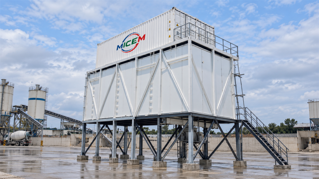
Industrial ice storage requires balancing incoming ice quality, holding time, and discharge mechanics. While long-term storage requires sub-zero refrigeration, simply lowering the room temperature will not prevent clumping or bridging. A reliable system pairs an accurate thermal setpoint with verified discharge performance under peak plant loads.
What Temperature Should Industrial Ice Be Stored At?
The target temperature for industrial ice storage is dictated by holding duration and inventory turnover rather than a single universal setting. Engineering standards distinguish between short-term process buffering and prolonged refrigerated preservation:
- Daily Turnover: ASHRAE notes that well-insulated bins operating in moderate ambient conditions can hold daily-turnover ice without mechanical refrigeration.
- Prolonged Storage: Requires dedicated sub-zero refrigeration to prevent gradual melting and fusion.
- Industry Benchmarks (WFLO Manual):
- Block Ice: Approx. −3.9°C (lowered to −9.4°C for high vertical stacks to resist basal crushing).
- Packaged Ice: −12.2°C to −3.9°C.
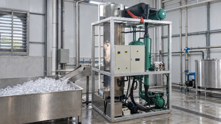
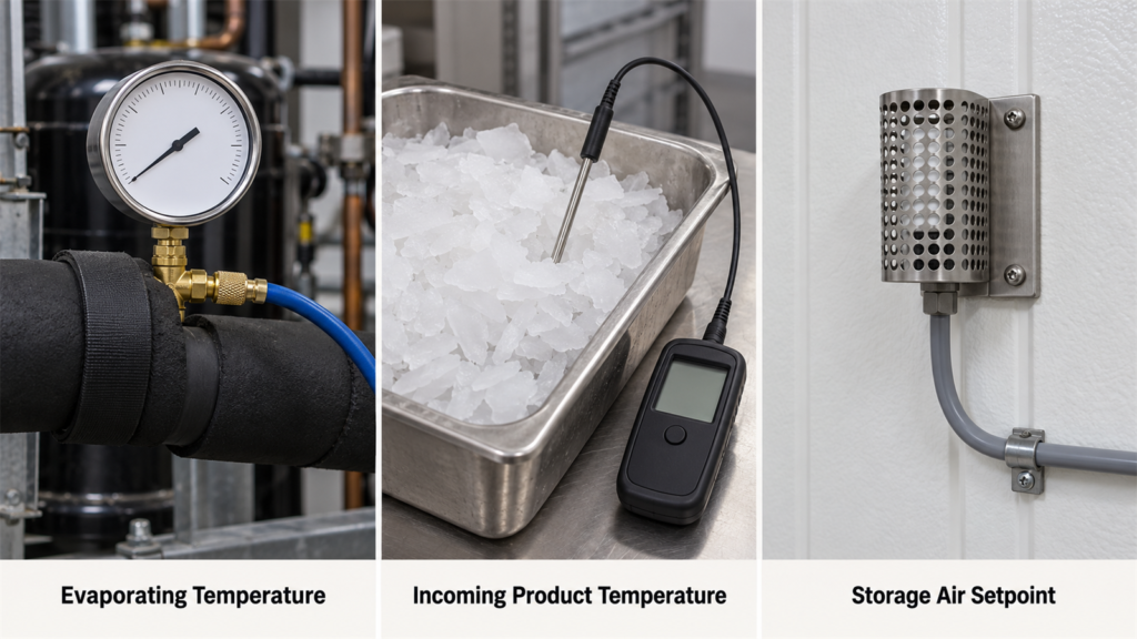
When specifying industrial ice machines and storage enclosures, distinguish between evaporating temperature, incoming product temperature, and storage air setpoint. Never copy the ice maker’s evaporator suction temperature directly into the cold room design.
Ice Storage Requirements by Ice Type
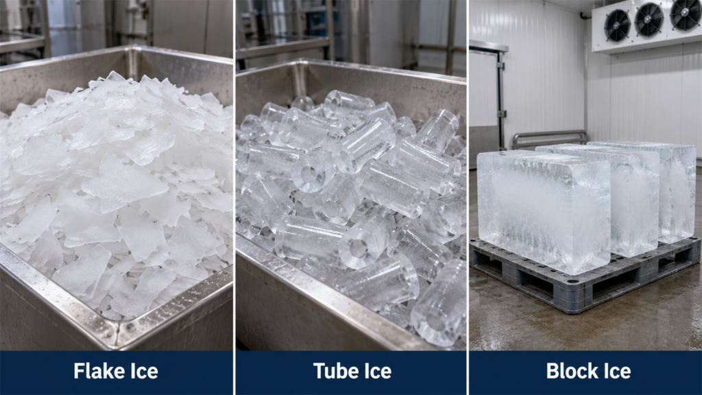
Different ice geometries behave dissimilarly in storage. Thermal setpoints, humidity control, and discharge mechanisms must match the specific morphology, surface area, and incoming moisture of the ice being handled.
Flake Ice
Harvested dry and subcooled (−5°C to −7°C), flake ice offers an initial margin against melting. However, its high specific surface area makes it prone to rapid heat absorption and pressure fusion. When evaluating flake ice selection, factor in bin agitation and automated rake recovery so flakes remain free-flowing for dosing rather than fusing into a solid block during static holds.
Tube Ice
Harvested via hot-gas defrost, tube ice discharges with a surface moisture film. Per WFLO guidance, mechanical dewatering or surface conditioning is essential before sub-zero storage; unconditioned surface water freezes contacting cylinders together. When consulting an ice type comparison, specify whether tubes enter storage loose, conditioned, or pre-bagged.
Block Ice
Intact blocks have minimal surface area and melt slowly, but tall stacks generate severe basal pressure that fuses contact points. Crushed block ice behaves like fragmentary ice, requiring entirely different handling. Prioritize stack stability, aisle clearance, and grab access over lower setpoints when expanding inventory.
What Factors Affect Industrial Ice Storage Conditions?
Selecting a room setpoint is only the starting point; maintaining stable storage requires managing the dynamic thermal, structural, and mechanical forces acting on the ice during day-to-day operations.
Storage Duration
Base storage sizing on the longest holding period—including weekends and unplanned downtime—rather than average daily throughput. Effective ice capacity planning incorporates mechanical first-in, first-out (FIFO) extraction; otherwise, fresh production channels over an increasingly compacted, unrecoverable base.
Incoming Ice Temperature and Moisture
Storage evaporators maintain ambient temperature; they are not blast freezers. Wet ice introduces a heavy latent heat load to the coils. Verify product temperature and visible surface moisture at the bin inlet rather than relying on nominal machine ratings, and account for harvest moisture variations in the bin design.
Heat Load
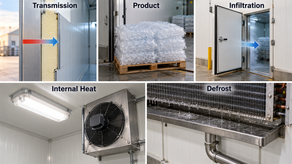
ASHRAE breaks refrigerated storage load into five components: envelope transmission, product sensible/latent heat, air infiltration, internal heat (motors, lights), and defrost heat. Offset higher summer heat loads with adequate refrigeration capacity and airflow—not by arbitrarily dropping the thermostat setpoint.
Ice Pile Depth
ASHRAE confirms that sustained pressure and time accelerate the fusion of fragmentary ice. Deep piles cause severe compaction at the bottom. Restrict pile depth to the breakaway torque limits of your discharge screw or rake system after a 48-hour standstill.
Why Ice Melts or Clumps During Storage?
Melting and clumping represent distinct thermodynamic failure modes within a storage system. Diagnosing the issue requires isolating thermal infiltration from mechanical compaction and incoming surface moisture.
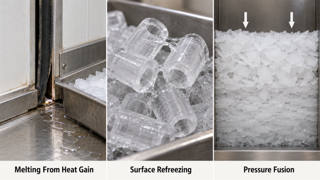
Melting From Heat Gain
A controller reading of −6°C does not ensure a uniform bin climate. Melting typically indicates localized thermal breaches: unsealed conveyor penetrations, worn door gaskets, or dead airflow zones. Map visible runoff against shift traffic and door-opening logs before adjusting the temperature setpoint.
Clumping From Refreezing and Compaction
Clumping stems from two distinct mechanisms:
- Surface Refreezing: ASHRAE explicitly warns that introducing wet ice into a sub-zero room causes surface water to freeze adjacent pieces into a solid mass. Lowering room temperature worsens this issue.
- Pressure Fusion: Sustained static weight causes particle contact points to weld together.
Diagnose whether blockages occur at the discharge throat (moisture issue) or deep in the pile (compaction issue) before modifying thermal setpoints.
How to Control Ice Storage Conditions?
Reliable climate control goes beyond adjusting a wall thermostat; it requires an integrated strategy linking refrigeration management, building envelope integrity, and automated discharge mechanics.
Temperature Monitoring
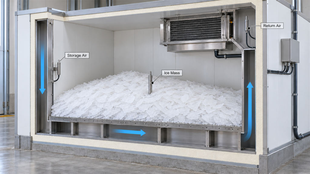
Monitor storage air, return air, and ice mass separately. Place calibrated probes across the perimeter, near loading chutes, and in the return duct. Cross-reference temperature data with SCADA door-switch and defrost logs to separate normal operational spikes from system failure.
Heat Gain Control
Maintain envelope integrity: inspect panel cam-locks, floor expansion joints, and transfer penetrations. Fit automated fast-acting doors or air curtains interlocked with discharge conveyors to prevent ambient moisture infiltration during processing delays.
Airflow and Defrost Management
Distribute airflow uniformly around the perimeter using jacketed walls or false plenums without blowing directly on the ice pile. Per ASHRAE, defrost cycles introduce temporary heat and moisture peaks. Terminate defrost by coil temperature or pressure, ensure drain pans clear condensate before fans restart, and verify fast pulldown.
Inventory Rotation
Enforce mechanical FIFO rotation. In tall bins, ice often “ratholes”—discharging through a center core while leaving stagnant outer rings that compact over time. Calibrate sweep rakes and schedule routine bin pump-downs to clear residual dead zones.
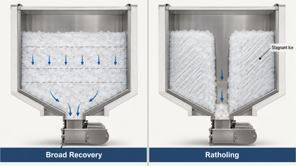
Ice Pile and Discharge Management
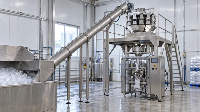
Interlock ice makers with downstream handling lines using high-level sensors to stop production before overfill binds mechanical drives. For facilities with complex layouts, multi-point discharge, or pneumatic conveyance, consult project engineers to validate bin geometry and drive torque against dynamic ice flow.
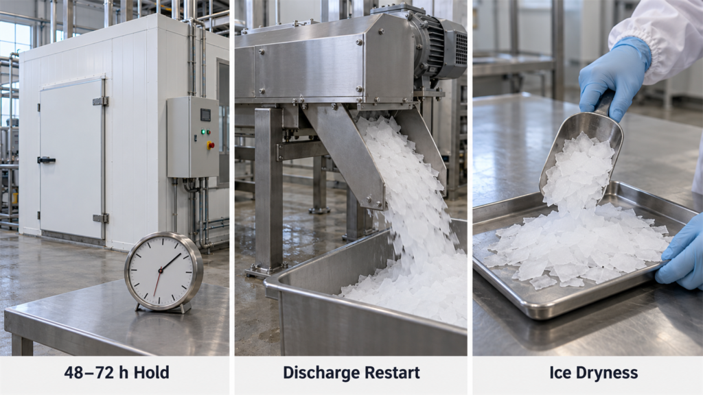
Commissioning Rule: Always test discharge restart after the maximum planned hold (48–72 hours). Testing only with freshly made ice will not reveal breakaway torque limits.
Operating Performance Checks
Validate performance during commissioning under worst-case conditions: peak summer ambient temperatures, maximum holding duration, and rated discharge capacity. Measure defrost recovery times, ice dryness, and discharge reliability. Treat repeated clumping or melting as mechanical or moisture issues first, adjusting temperature setpoints only as a last resort.
Implementation Checklist
Use this engineering checklist to specify, verify, and commission industrial ice storage systems before commercial handoff:
- Define the storage duty: Ice format, incoming moisture, maximum holding hours, buffer tonnage, and discharge rate.
- Separate temperature specifications: Distinctly document storage air, product, and evaporator suction temperatures.
- Verify mechanical handling: Confirm FIFO flow, pile depth limits, drive breakaway torque, and bin-full interlocks.
- Commission under static hold: Validate discharge recovery after a 48–72 hour dwell period under full heat load.